
Negative Impedance Converter Altair University
The negative impedance converter ( NIC) is an active circuit which injects energy into circuits in contrast to an ordinary load that consumes energy from them. This is achieved by adding or subtracting excessive varying voltage in series to the voltage drop across an equivalent positive impedance.

What is the basic idea behind the negative impedance converter? How is
Negative impedance converter (NIC) circuits violate Foster's Reactance Theorem [1] because those circuits provide the negative values of resistance, capacitance and inductance. Thus, NIC circuits are also known as non-Foster circuits.

What is the basic idea behind the negative impedance converter? How is
The negative impedance converter (NIC) is a one-port op-amp circuit acting as a negative load which injects energy into circuits in contrast to an ordinary load that consumes energy from them. This is achieved by adding or subtracting excessive varying voltage in series to the voltage drop across an equivalent positive impedance.

Can we present the negative impedance converter (NIC) as a balanced bridge?
The negative impedance converter (NIC) is a one-port op-amp circuit acting as a negative load which injects energy into circuits in contrast to an ordinary load that consumes energy from them. This is achieved by adding or subtracting excessive varying voltage in series to the voltage drop across an equivalent positive impedance.
An Introduction to Negative Impedance Converters
What is the use of the true negative impedance? What is the difference and what is the common between the true and differential negative resistance? You will find answers to all these questions in this exciting circuit story about the mystic phenomenon. The true negative resistance is closely related to the differential negative resistance.

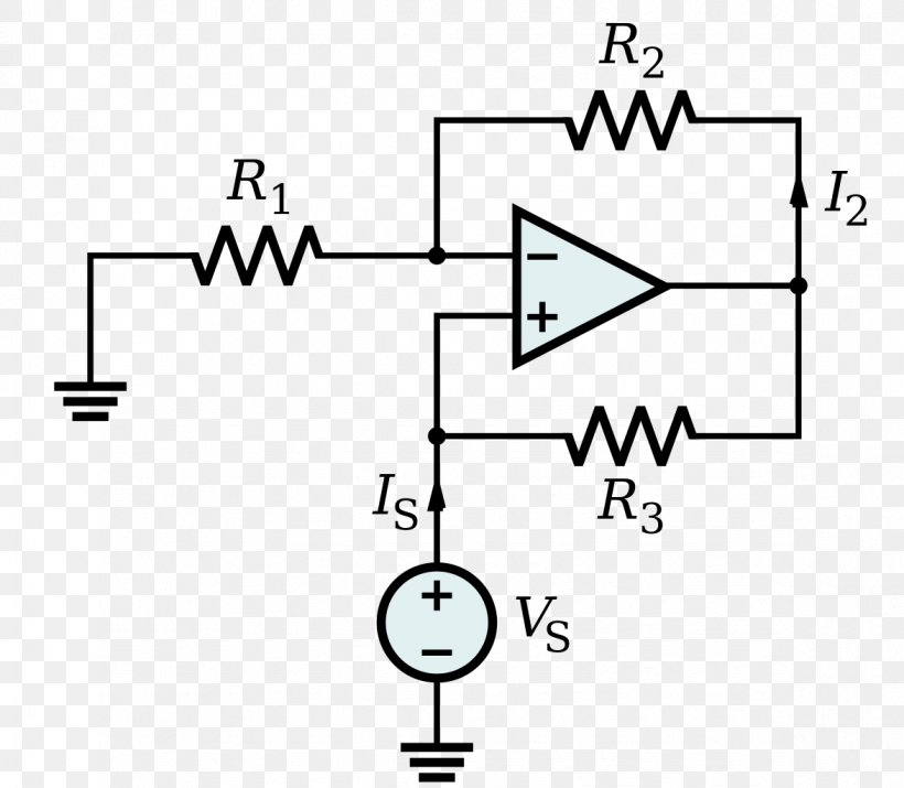
Negative impedance converter built by operational amplifier according
The Negative Resistance Converter The consequences of a device that could have this property are puzzling. All ordinary devices have some internal resistance inherent to their construction that automatically dissipates energy when a current is flowing.

What is the basic idea behind the negative impedance converter? How is
Abstract: The authors describe the negative impedance converter, a simple analog building block which can be readily implemented in CMOS. They present a circuit based on the inverse-function approach, providing precise temperature-compensated linear operation.

Lab 7 Op Amps II Instrumentation LAB
The negative impedance converter (NIC) is an op-amp circuit which acts as a negative load. This is achieved by introducing a phase shift of 180° (inversion) between the voltage and the current for a signal source. There are two versions of this circuit - with voltage inversion (VNIC) and with current inversion (INIC)..

Negative Impedance Converter Circuit Cellar
A negative impedance converter (NIC) is a clever circuit, the analysis of which is a favorite exercise set by engineering lecturers everywhere. It's not often used in practice, but it's well worth having in your design kit-bag. I'll show you two real-life applications once we get through the analysis—which is not as hard as it might seem.
Proposed CMOS negative impedance converter circuit. Download
Gm with negative. Reference: S. Szczepanski, J. Jakusz and R. Schaumann, "A linear fully balanced CMOS OTA for VHF filtering applications," in IEEE Transactions on Circuits and Systems II: Analog and Digital Signal Processing, vol. 44, no. 3, pp. 174-187, Mar 1997. Floating bias source: Ma1-Ma3 & Mb1-Mb3.
Reinventing Negative Impedance Converter (NIC)
Negative-Impedance Converters Abstract: The conditions under which an active device exhibits an input impedance at one terminal pair which is exactly the negative of the load impedance connected to the other terminal pair are discussed.

What is the basic idea behind the negative impedance converter? How is
This paper is devoted to the device properties of the negative-impedance converter (NIC), the derivation of potential NIC circuits and their compensation in order to achieve an exact NIC. The behavior of the NIC as a function of frequency and means of extending its useful frequency range are presented. Attention is also devoted to the sensitivity of the NIC to variations in active and passive.

Reinventing Negative Impedance Converter (NIC)
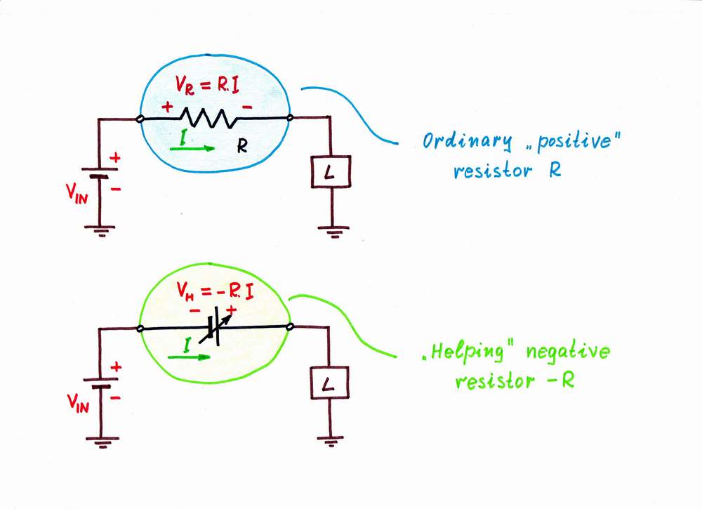
Current Circuit: Negative Impedance Converter The circuit on the left converts a positive impedance to a negative impedance. So, for example, instead of Ohm's Law (E=IR) it causes a resistor to obey E=-IR. The circuit on the right shows a positive impedance (a 150 ohm resistor) for comparison.

Negative impedance converter active circuit implementation of the
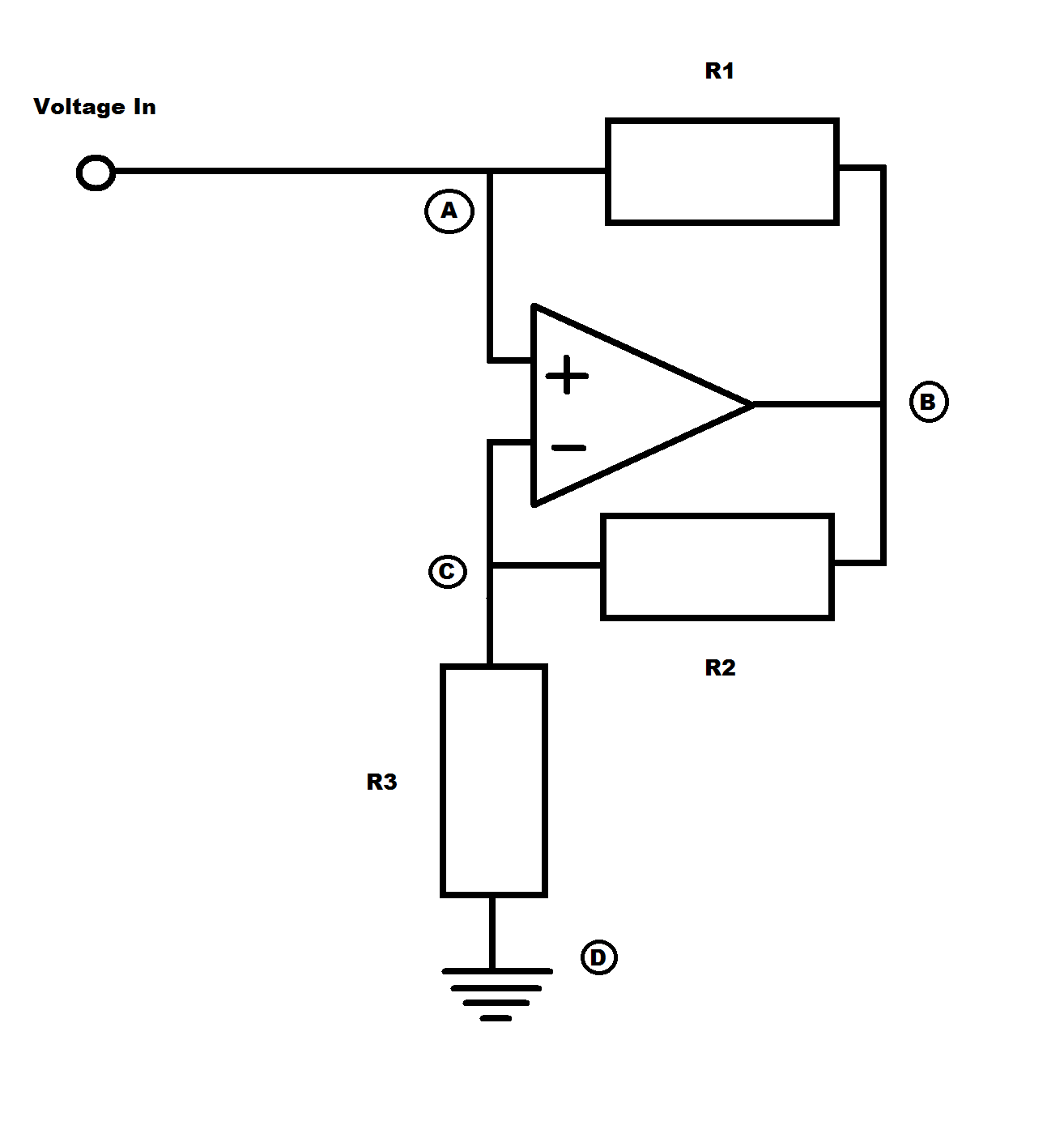
A generic NIC, shown at right, is a negative impedance converter. Looking into V in, the NIC appears to have an impedance -Z to ground. In other words, the circuit inverts it internal impedance Z to -Z.: Construct the circuit below. Use matched, 1%, precision resistors.To match resistors, start with ten to twenty of each value.

Electronic How to analyze an opamp based negative impedance
The negative impedance converter (NIC) is a universal circuit - it can act either as VNIC or INIC Contents 1 What is negative impedance converter? 2 How to create negative impedance converters 2.1 Inverting the voltage polarity 2.2 Inverting the current direction 3 How to implement conceptually the resistance inversion 3.1 V-inverted resistor
Negative Impedance Converter Operational Amplifier Negative Resistance
Negative impedance converter refers to a two-port network whose electrical characteristics when looked from outside presents as a negative impedance (Fig. 1), as the meanwhile according to the type of input control signal, it can be divided into voltage-controlled impedance converter and current- controlled impedance converter.